Serial vs Parallel

So far we've been using solitary resistors* in class, but they don't always have to be so lonely. Introducing... serial and parallel resistors!
* I'll use "resistor" as a blanket term for the typical resistor and all variants; potentiometers (AKA variable resistors), LDRs (AKA Light-Dependent Resistors or photoresistors), vegetables, your skin, pencil graphite, anything you can use to limit current!
Serial resistors
Serial means one-after-the-other. Think episodes of a show or the Serial podcast or, uh, a serial killer. Serial resistors in schematic form look like this:

The total resistance across serial resistors is straightforward. Just add 'em up! If A is 1k, B is 2k, and C is 3k, then the total is 6k.
Parallel resistors
Parallel means lined up. Think geometric lines that never intersect or a stack of pancakes, stuff like that. Schematically:
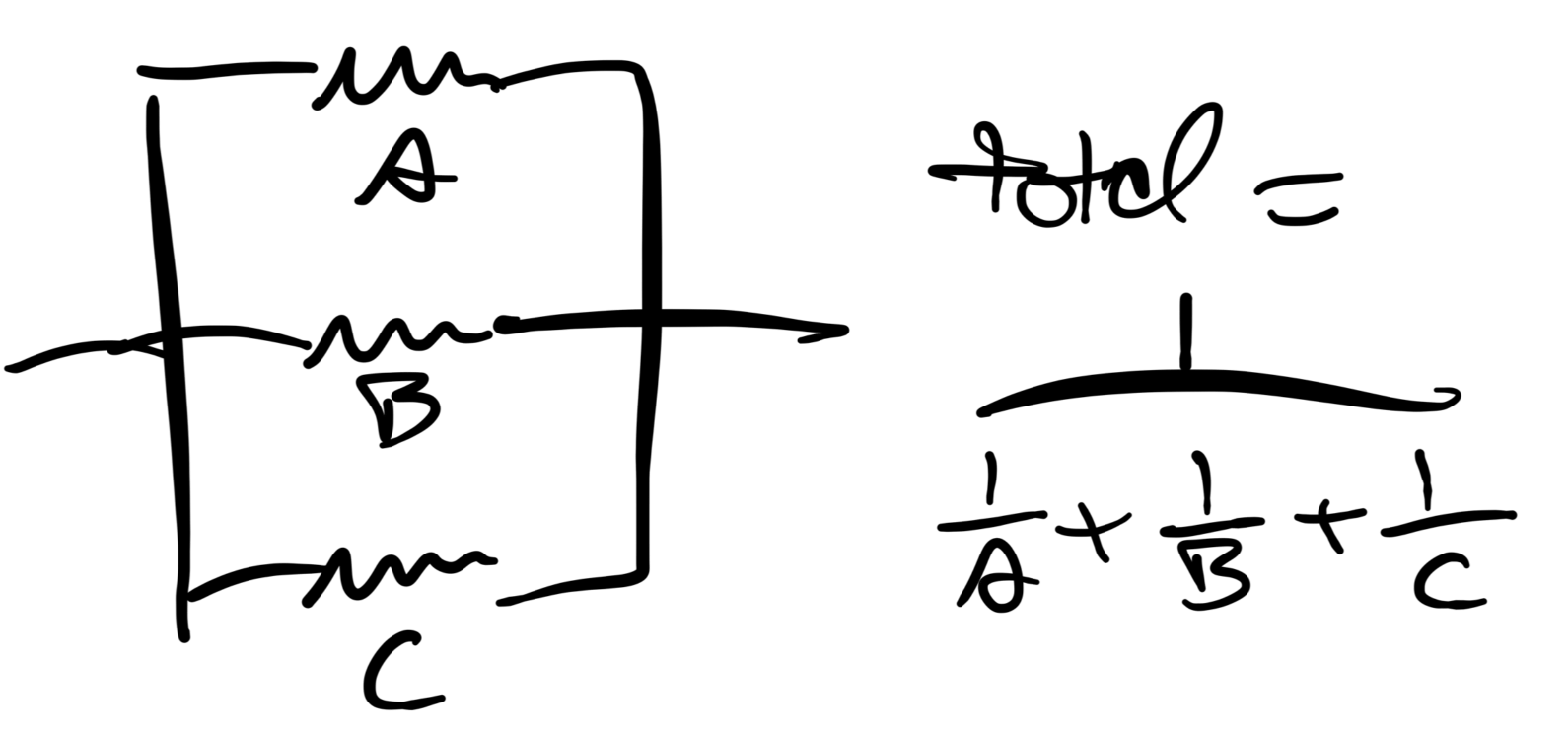
The total resistance across parallel resistors isn't nearly as easy as it was for serial, huh? If A is 1k, B is 2k, and C is 3k, then the total is... you guessed it... 545ohms.
I'm not smart enough to internalize that, so here are my tricks:
- The total for parallel resistors is always less than the smallest resistor value. I like to imagine a car on a congested highway, going a little bit faster than its fastest lane with decisive lane-changing? IDK.
- Google "parallel resistor calculator" and let a random website do the math for you
Let's make a keyboard!
We know that our oscillator's frequency is set by a capacitor and a resistor, and we've mostly been getting variable frequencies by using potentiometers or LDRs.
Review our typical, single-resistor oscillator schematic:
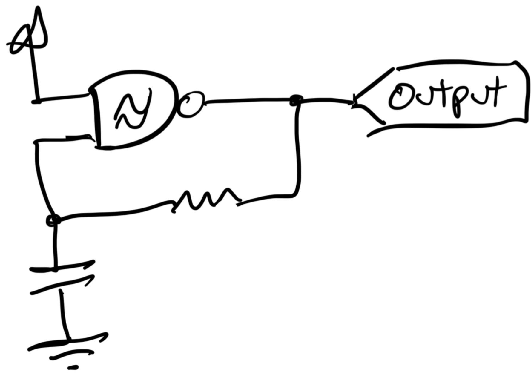
I don't love the piano layout, but I do like the idea that I can hit some key/switch/button, and it will play a specific note. Let's implement what we just learned and swap out the single resistor for, say, three resistors and three matching switches.
In other words, let's make a three note keyboard!
Serial resistors in a relaxation oscillator
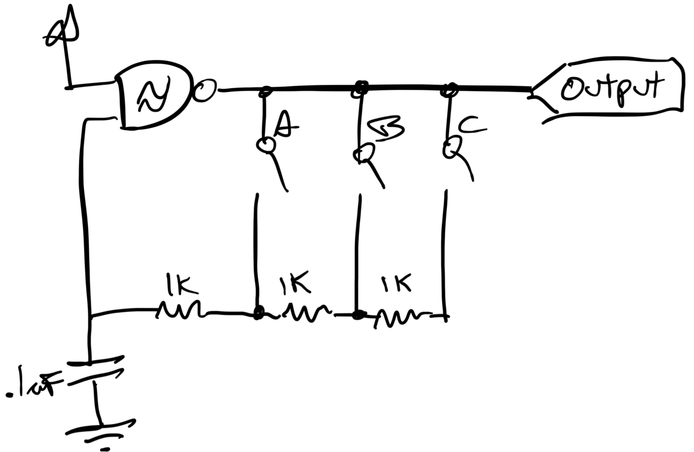
Pressing button A produces 1k for the oscillator, B makes 2k, and C makes 3k. And if you press A and B and C, the total resistance the oscillator will get is... what?
It's 1k. Electrons will take the path of least resistance, so it will always be the smallest switched resistor value. The other resistors from B and C don't matter. That's kind of unexpected, right?
At an interface level, however, it's very intuitive. The highest frequency note takes precedence over any lower ones. Musicians call an instrument like this "high note priority."
Button C will make the highest resistance and play the lowest frequency of the three, so I want its button to be leftmost as it would be on a piano. On a breadboard, the switches and resistors for this schematic could look like this:

If you want these buttons to play the first three notes of a C Major scale, you can use potentiometers and tune them all into place with an instrument tuner. The gotcha is that, because low notes rely on high notes, the instrument will go out of tune when any high note drifts.
Parallel resistors in a relaxation oscillator
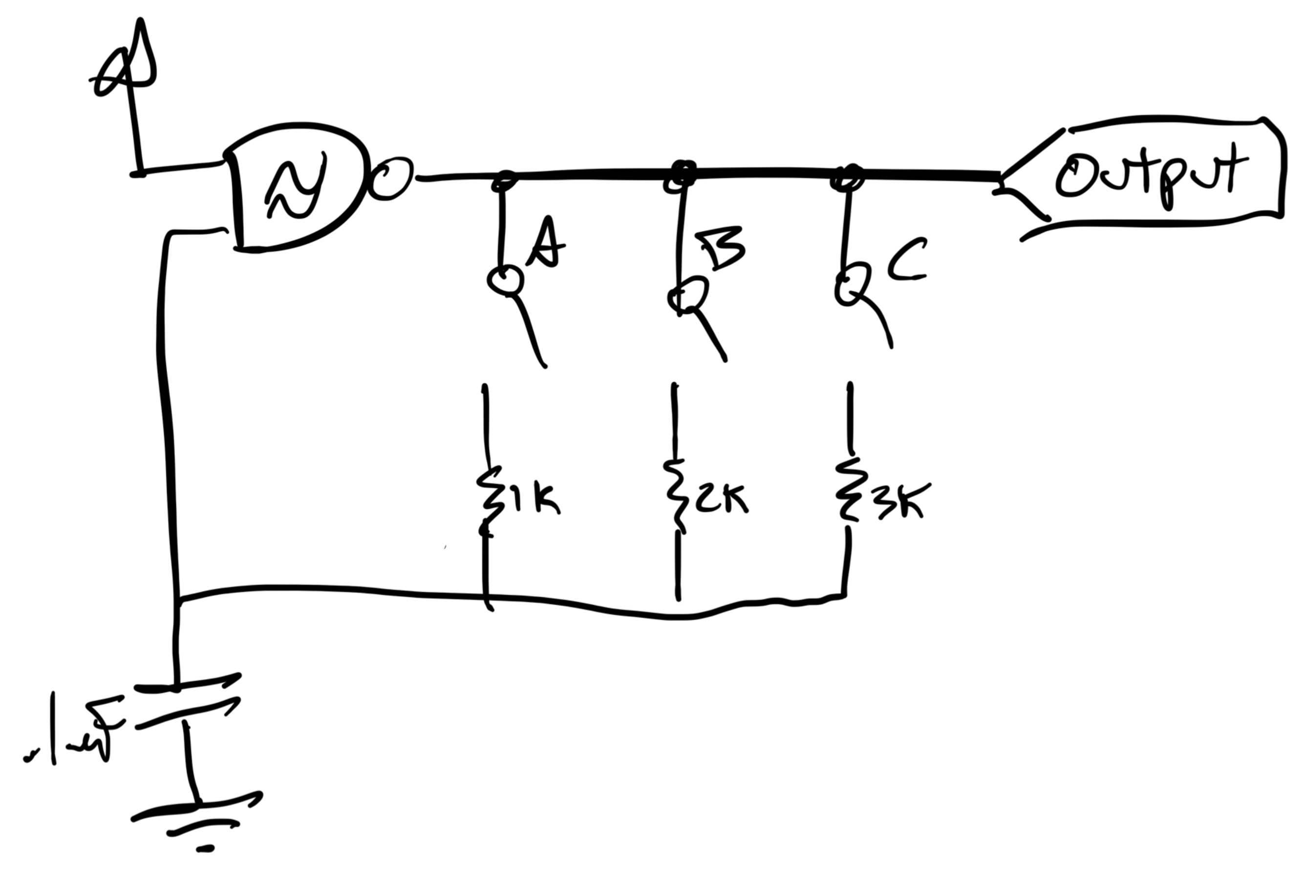
And the switches and resistors on your breadboard, again ordered so lower notes are on the left:
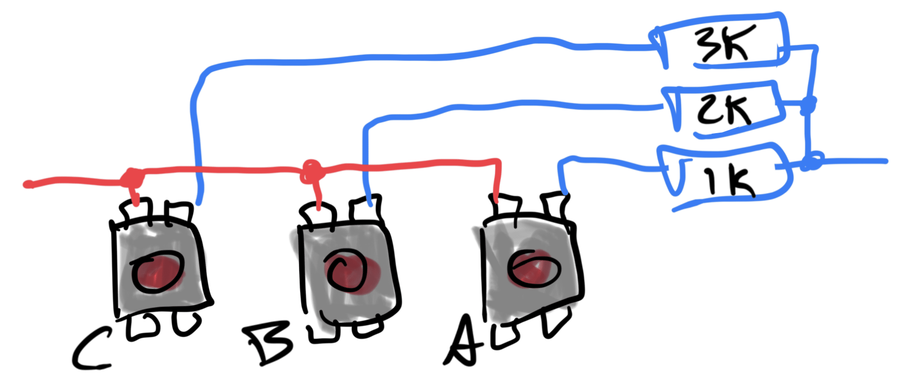
The resistor values are changed to match the behavior of the serial example. Button A produces 1k, B 2k, and C 3k. The resultant frequencies will be theoretically identical.
But what happens when you press all three buttons simultaneously? According to the math above, the oscillator receives 545ohms, which would make a frequency much higher than the otherwise highest note. Probably not what the player had in mind.
So the con of this approach is the unexpected behavior of weird notes when playing chords or trying to glide, but the pro is that, because the total resistance values don't rely on each other, notes tune independently.
Which one to pick
Which is better for wiring up resistors for our relaxation oscillator, serial or parallel? I personally like serial for user experience reasons, but I have made and enjoyed parallel versions.
A better question might be... Regardless of which you choose, what are the design ramifications of this kind of switches-as-frequency-selector? Are there cultural expectations of a piano keyboard that a random knob doesn't have? What do we gain, how are we burdened?
Other uses for serial/parallel resistors
- Shift a pot's range by putting a resistor before/after it in serial. For example, a 10k pot + 1k resistor creates a range from 0-10k to 1k-11k. If the frequency pot on your oscillator is unusably high at one end of its sweep, this is a great way to bring it back down to earth.
- The math on this is beyond what I can fit in a bullet point, but a resistor in parallel with two legs of a linear pot can make it behave logarithmically. See "the Secret Life of Pots".
- Resistors in serial are sometimes called "resistor ladders," and, when voltage is applied through them, they act as "voltage ladders". These are used to convert digital signals to analog and vice versa. Something to look into if you're into audio DACs!
- Remember the CD4051 multiplexer? It's a fancy switch! Serial resistors across its channels make a kind of binary-controlled variable resistor, an overwrought version of another chip called a digipot. See if you can figure out the schematic for it.
Addendum: Failed car analogy
I thought I could use cars as a visual analogy for serial/parallel resistors, but I was wrong.
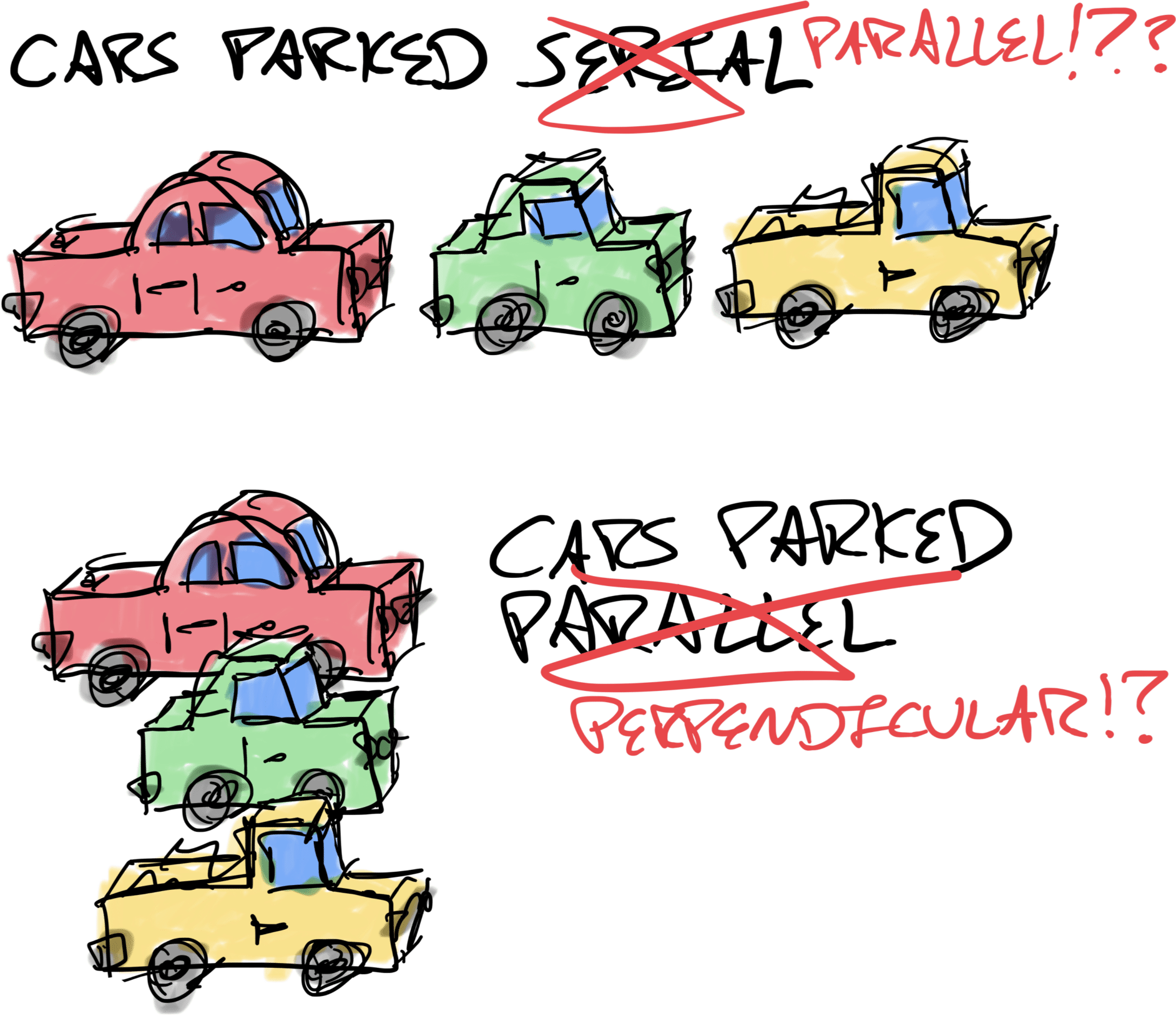
Why? Why?!
Answer: "Parallel" and "perpendicular" are in reference to the curb, not the other cars.