Gotchas!
I wanted to quickly write on a couple things I’ve noticed in class that have tripped people up:
- This stuff is small! Parts are genuinely, physically hard to see.
- It's strange! Even when we can see what's in front of us, it's unfamiliar.
- Its instructions are unclear! Hmph!
Let's see what we can do...
1. Small stuff
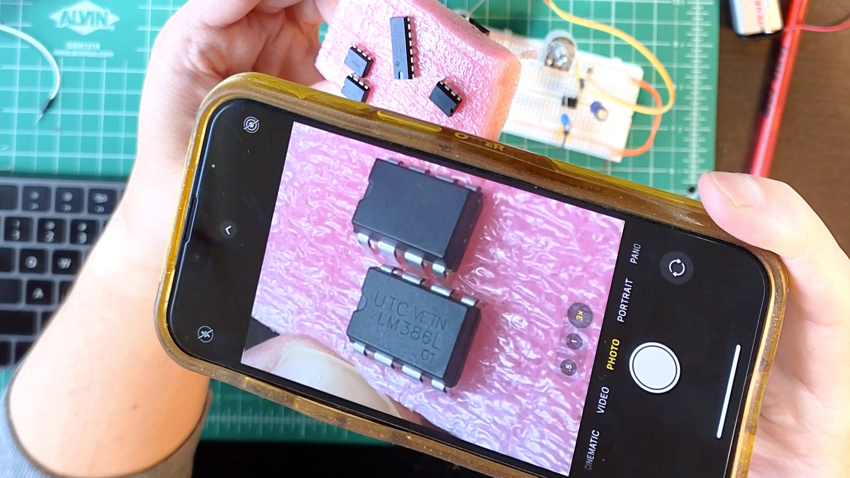
- You can't see without good lighting. Start there.
- Make like grandpa and break out the magnifying glass. In a pinch, your phone's camera also makes a fine magnifier!
- When appropriate, label components so you aren't relying solely on good eyesight. Resistor color codes are notoriously hard to read and your kit's are labelled specifically for this reason. I like to label IC chips. You can also organize your parts into labeled bins, etc.
- The floppy jumpers are excellent for quick wiring but can turn into a confusing jungle when there are lots of them. You can try optimizing for shorter wires, or break up one spot with lots of connections into multiple spots on the breadboard, or develop a convention about which colors to use for what function. Methodical patience goes a long way here. Of course, you can make your own wires or buy pre-cut jumper kits too!
2. Strange stuff
The two big unfamiliarities I see are for the breadboard and then the IC chips.
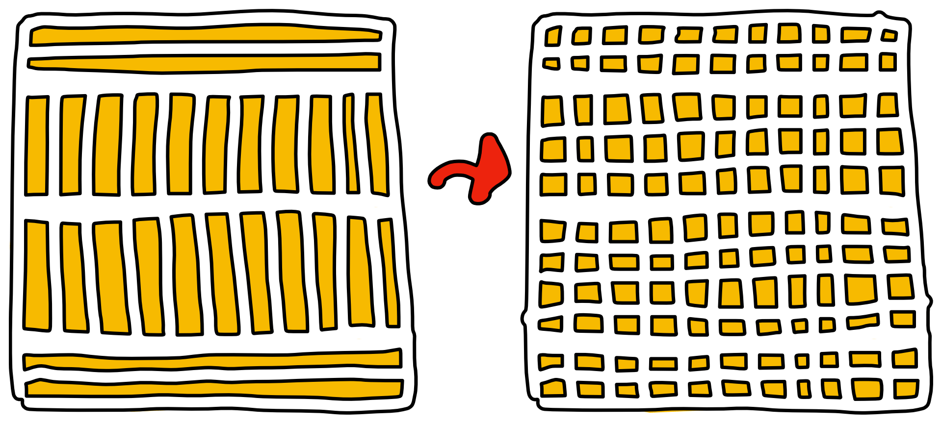
Recall that under the hood of your breadboard are rows and columns of conducting metal that grip and connect anything that's plugged into them. Crucially, anywhere there's a gap in the metal there won't be a connection!
As for IC chips, with the its notch/dot pointed left and its text facing you to read, its pins are ordered counter-clockwise starting at the lower left. This is how they'll be on your breadboard.
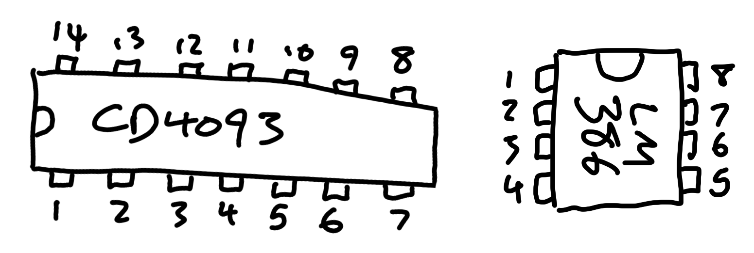
It's common to see chips drawn in portrait mode with the notch at the top too. It's just a rotated view — pin order is identical.
Different chips will have different pin counts but will thankfully all follow the same pin ordering convention.
3. Unclear stuff
Perhaps counterintuitively, the best remedy for unclear instructions is to make them shorter and more technical.
Here are three not-incorrect instructions on how to light an LED:
- Connect a nine volt battery snap to a new or freshly charged nine volt battery. Connect one side of a green gator wire cable thing to the exposed metal end of the battery snap's black wire and a different but also green gator to the other wire, the red one, the metal part. Find a resistor with bands colored orange orange brown and connect one leg to the other end of the second green gator and the other leg of the resistor to a yellow gator clip. Notice how the LED has a long leg and a short leg? Clip the other end of the yellow gator to its short leg Finally, the longer leg of the LED connects to remaining clip on the first yellow gator.
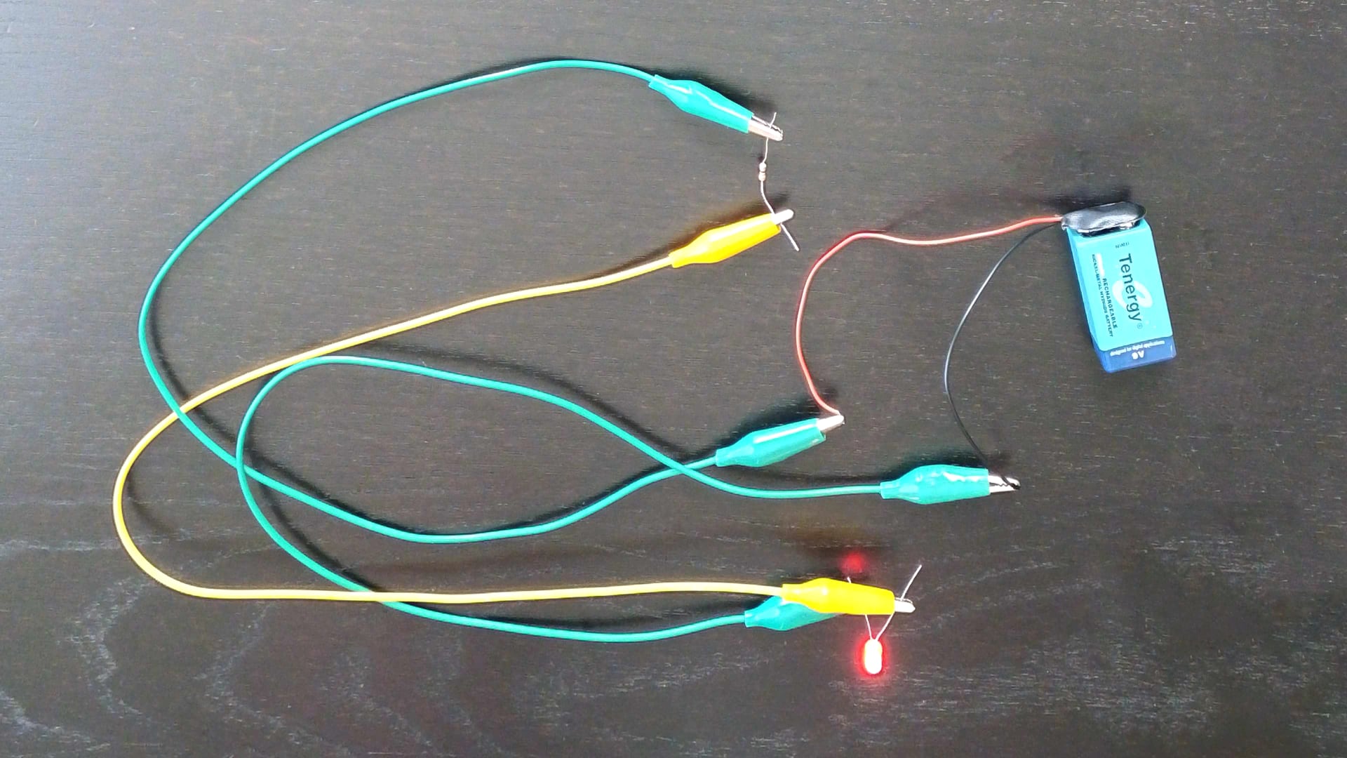
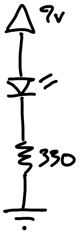
Which do you prefer? Why?
(That was all a lead-in for this week's lesson on schematics. You got that, right?)
Other Debugging Tips

- Get your rubber duck and start talking to it, out loud. Explain the problem you have and what you're doing about it. Somehow, verbally articulating an issue can manifest a solution. It works! It's real! I've done it for years! (See also: Shisa Kanko)
- Build incrementally and test as you go. Light the LED → make a NOT gate or permutate the NAND (see below) with the CD4093 → convert it into an oscillator and strobe → make it faster! → connect it to your amp → and so on. Fixing small, incremental changes is much easier than fixing a whole, completed circuit.
- Practice being descriptive-but-succinct when you describe things. "Pin 3 to pin 3" isn't nearly as valuable as "4093's pin 3 to 386's pin 3". Do this in your head, to your rubber duck, in class, and to any loved ones who will listen.
- Draw things, take notes, doodle. Interpret what I'm saying into your own words.
- Be kind to yourself! Be patient with yourself!
Exercise: Permutate the NAND
I used to do this in class but we ran out of time. (It's also not super exciting so oh well whataryagonnado.) Still, it's a good, simple exercise to see how a CD4093 NAND functions and get practice connecting jumper wires around. When all else fails and nothing seems to work, build this.
- Power CD4093: pin 14 to +, pin 7 to -
- Default inputs: pin 1 to -, pin 2 to -
- Show output: pin 3 to 330 resistor to LED (positive/long leg) to -
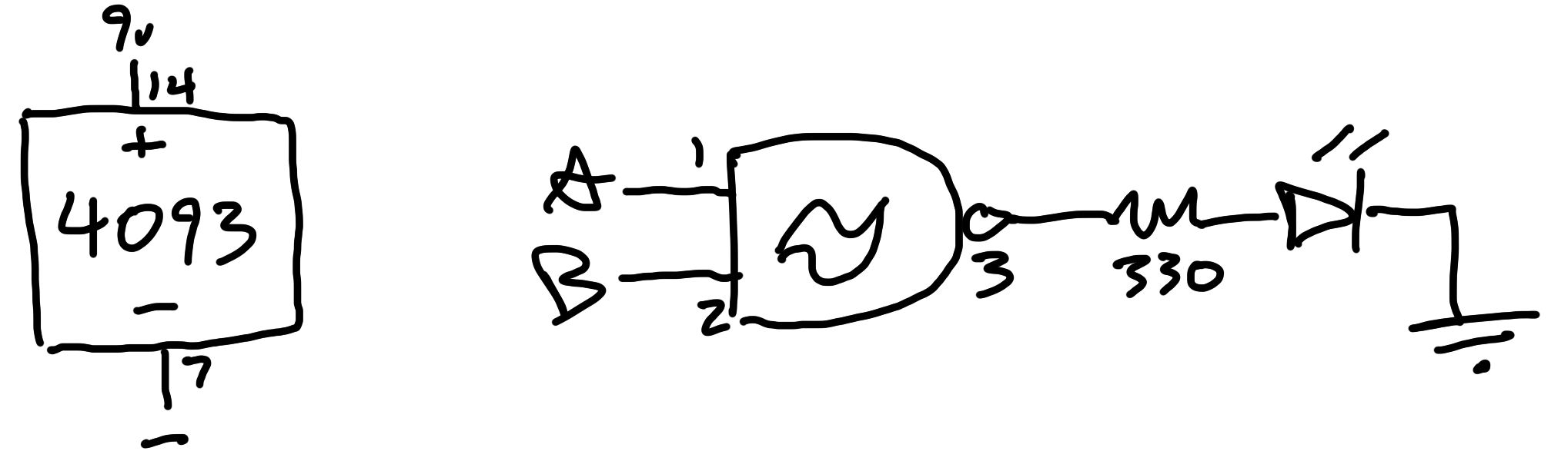
Finish the truth table by alternating pins 1 and 2 on the + and - power rails. If the LED lights, the output is +; if not, it's -.
| Pin 1 Input A |
Pin 2 Input B |
Pin 3 Output |
|---|---|---|
| - | - | |
| - | + | |
| + | - | |
| + | + |
Did it work as you expect?